Heathkit SB-200 Linear Amplifier
Restoration and Modification
Heathkit History
Heathkits were products of the Heath Company, Benton Harbor, Michigan. Their products included electronic test equipment, high fidelity home audio equipment, television receivers, amateur radio equipment, electronic ignition conversion modules for early model cars with point style ignitions, and the influential Heath H-8, H-89, and H-11 hobbyist computers, which were sold in kit form for assembly by the purchaser. For more history see http://en.wikipedia.org/wiki/Heathkit
SB200 History
The Heath SB-200 was introduced in 1964 and sold in that year for $200. It was last produced in 1978 when the SB-201 was introduced without 10 meter capability due to the FCC laws governing the manufacture of linear amplifiers for that frequency range. The SB-201 was manufactured until 1983. The SB-200/201 were manufactured longer than any other Heath SB product. The SB-200 is a compact and relatively lightweight linear amplifier. It is rated at 1200 watts input PEP and 1000 watts CW. It uses two 572B tubes and requires about 100 watts of drive. Heath used American made tubes but today in 2013 the 572B is only being manufactured in China and the quality of the tubes is considered to be not as good as those originally sold with this amplifier (see my note on this below) but if you get a good pair you should still be able to achieve a solid 600-700 watts of output.
Heathkits are ripe for modifications mainly because they were made to be as inexpensive as possible. I would not say they necessarily cut corners but if they could make a great rig with 100 parts and an OK rig with 80, they chose the 80. It is also easy to say in 2013 why didn't they do something different in 1963. Fifty years is a long time in technology. The solid-state devices and the many other parts I used in this modification did not exist in 1963 when this product was under development. The SB-200 is also an easy piece of equipment to modify both physically and because it is not rare. While some would want to absolutely keep it stock this is often not very practical for an operating piece of equipment. My rule is no holes in the front panel but inside and the rear panel are OK. Making a piece of equipment better, more useable, and safer actually increases its longevity.
My SB200 Project
(Click any photo to see a larger view)
I received a call from a local ham's widow last spring asking for my help in disposing of her deceased husband's equipment. One of the items was a Heath SB-200 Linear Amplifier. It looked to be in good condition so I offered her a reasonable price for it and brought it home. It was Spring and going into summer so inside projects were not on my agenda. Once winter arrived and my Johnson Ranger project was complete I started work on the SB-200. I had been doing planning work almost since I got it, reviewing the plethora of SB-200 information on the Internet. I ordered the Harbach power supply, SoftStart, and SoftKey modules. When I finally started the project in earnest I had a pretty good idea what I wanted to do but like all of my projects the end result was quite different then I had imagined.
The SB-200 I bought was in good physical condition. Inside it was reasonably well assembled. I know it had at least two owners and probably more. The only modifications were a 12 volt DC relay with a power source off of the 6.3V line to key the higher voltage stock relay circuit and a toroid AC line filter. I later found the Plate RF choke was cracked at the base where the screw threads are and not repairable. I found a used one on Ebay. In going over the all the mods on the Internet for the SB-200 I picked some that made sense to me and then in some cases took it a step further. Coincidentally about the time I started the project I received my February 2013 Electric Radio Magazine. In that issue is an article titled “The HB-600 Linear Amplifier” by Mike Bohn, KG7TR. I started to communicate with Mike via email and he was very helpful with some of the questions I had about his design and linear amplifiers in general. I used, in a slightly different fashion, his bias method.
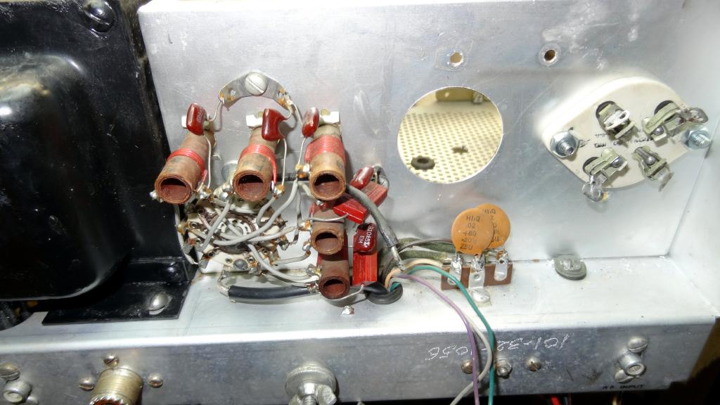
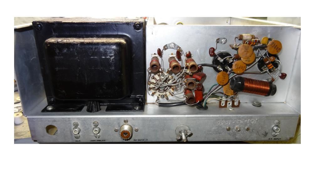 The before and during mods photos. This shows the rear panel with the line cord removed.
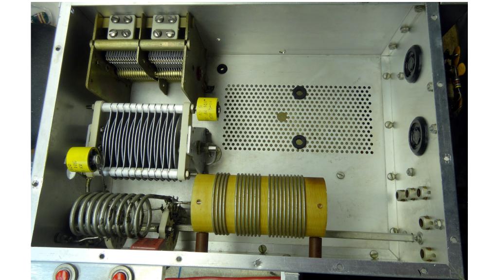 The RF deck with 572B's and RF choke removed.
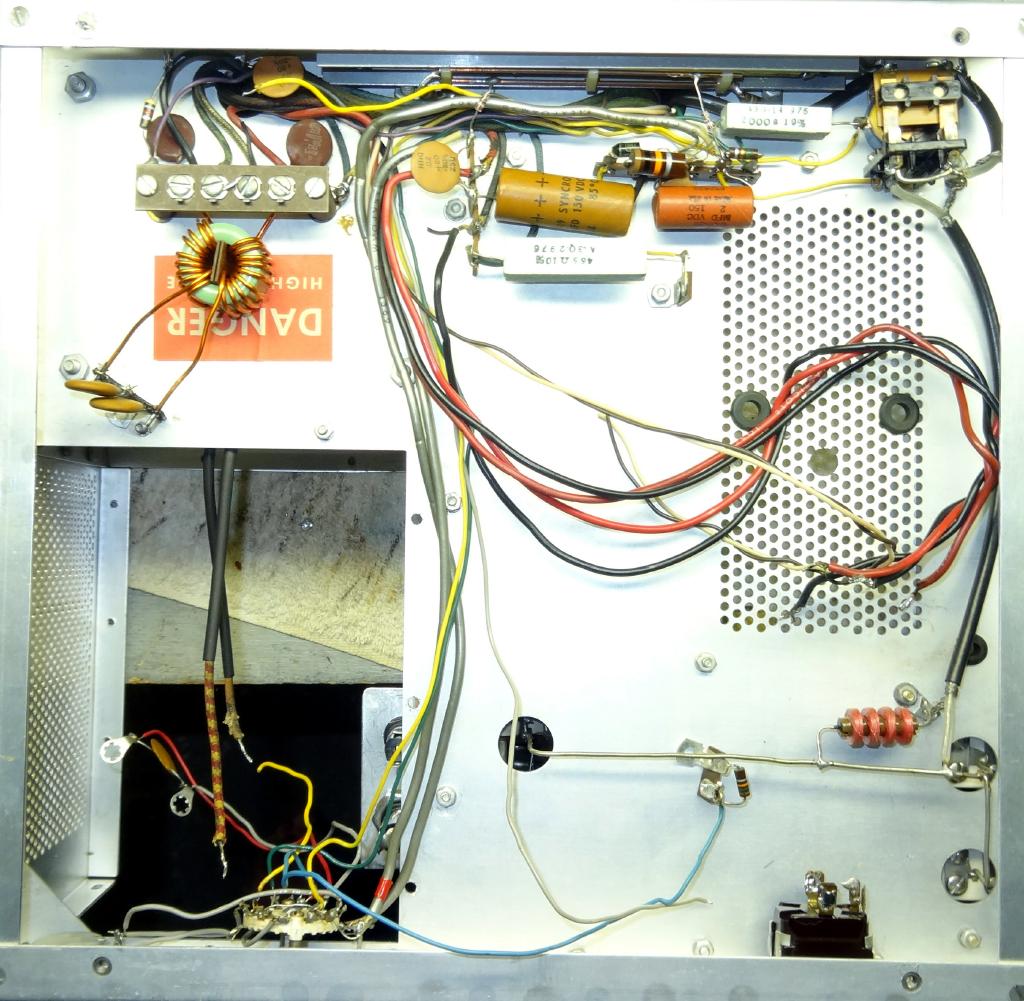 Underside view with fan, HV board, and some wiring removed.
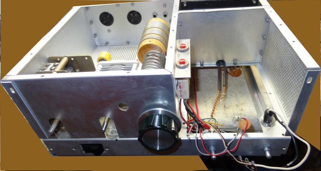 Front view with front panel and HV board removed.
I assembled the Harbach boards first. There are well made and a pleasure to assemble. I assembled the SoftKey module but determined that I was not going to use it in this mod because of my complete change of the bias and PTT circuits. I wound a new filament choke using a larger Amidon core and many more turns of wire.
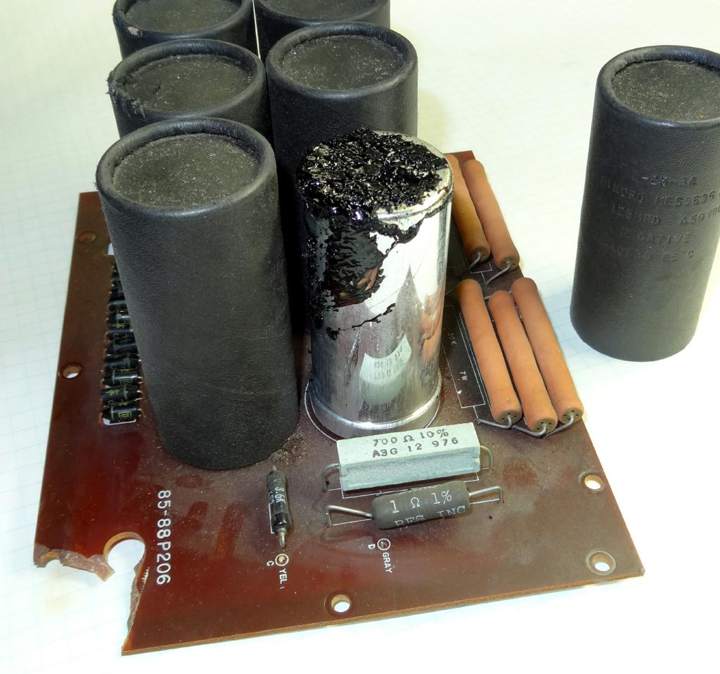 The old Heath Power Supply board removed and ready for the trash.
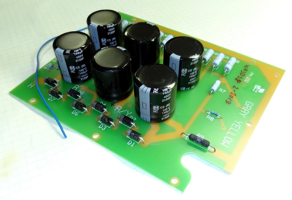 The new Harbach Power Supply board assembled and ready for installation
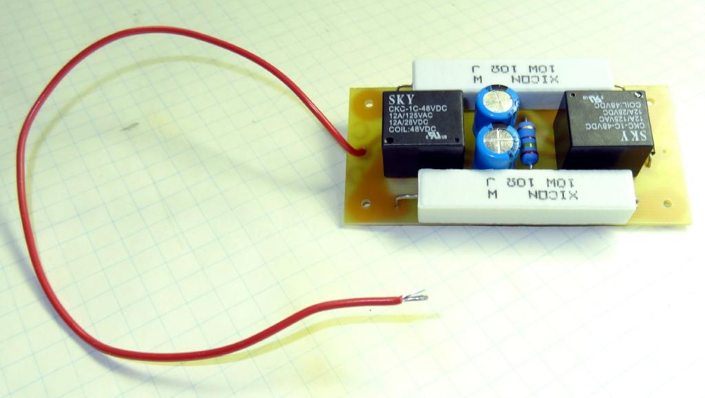 Assembled Harbach SoftStart module.
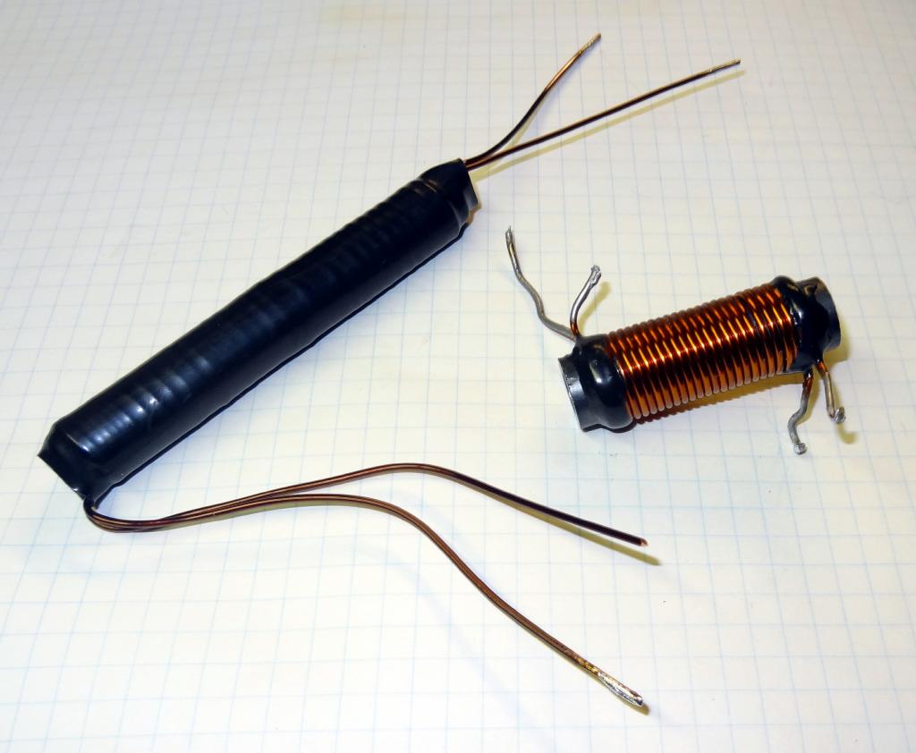 The old and new Filament chokes. The old choke measured about 9uh and the new over 30uh.
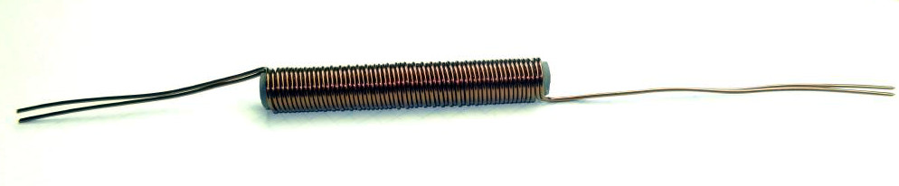 Filament choke before heatshrink coating was added.
Here is the list of the things I did in my restoration/upgrade of the Heath SB-200
- All wiring was removed and replaced with Teflon.
- A heavy (14ga) 3 wire power cord was installed.
- Unit was permanently wired for 120VAC operation.
- Circuit breakers were removed and replaced with a single fuse.
- Ferrite choke and capacitor RF filter on the AC line.
- AC power relay added to reduce the load on the front panel switch.
- Harback SoftStart module added.
- A transformer was added (25.2VCT 450ma) for the 12V and Bias voltages.
- Original fan was removed and replace with a large 12V muffin fan.
- Input RCA connector replaced with a BNC
- Entire bias system redesigned.
- Antenna relay replaced with a 12V relay.
- Control board added for the additionally required components.
- High voltage board replaced with Harbach module.
- Meter pilot lamp replaced with LED's.
- Original 572B tubes sockets replaced with ceramic sockets.
- Original filament choke replaced with larger inductance choke.
- Meter protection diodes added.
- Adjustable ALC added.
Virtually all of the original Heath wiring was replaced with Teflon wiring. Sizes used were number 22, 18, and 12 and the original colors were matched where possible. 18KV CRT wire was used for the short section of high voltage wiring.
The way that Heath switched between a 240V and 120V primary was kind of weird and did not work well in the 120V arrangement. I intended to make this a strictly 120VAC wired SB-200. The total draw is somewhat less than 12 amps and suitable for any 20A/120V circuit with plenty of margin. The transformer has dual primaries which Heath routed through two 8A circuit breakers mounted on the top panel. One breaker ended up in the neutral circuit which is not good. I completely rewired the primary circuit which can be seen in the schematic. A new heavy 14 gauge power cord from a discarded air conditioner was installed. The primary is switched with a power relay to keep current off of the precious front panel switch and power is routed through the Harbach SoftStart module. A ferrite RFI filter was added on the primary wires upon entering the chassis. The primary is protected with a single fuse mounted in place of the original circuit breakers. A second fuse protects the added low voltage power supply.
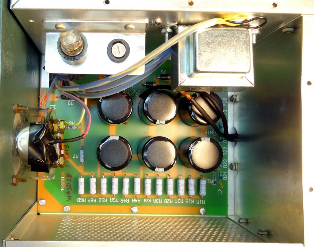 View showing fuses mounted in place of circuit breakers, Harbach power supply board installed, and new low voltage transformer. New high intensity LED's were fastened in the existing pilot light hole which had been melted
to a much larger hole by the original pilot lamp. Tape is used to reseal around the hole. The meter has back to back diodes installed for protection.
View showing fuses mounted in place of circuit breakers, Harbach power supply board installed, and new low voltage transformer. New high intensity LED's were fastened in the existing pilot light hole which had been melted
to a much larger hole by the original pilot lamp. Tape is used to reseal around the hole. The meter has back to back diodes installed for protection.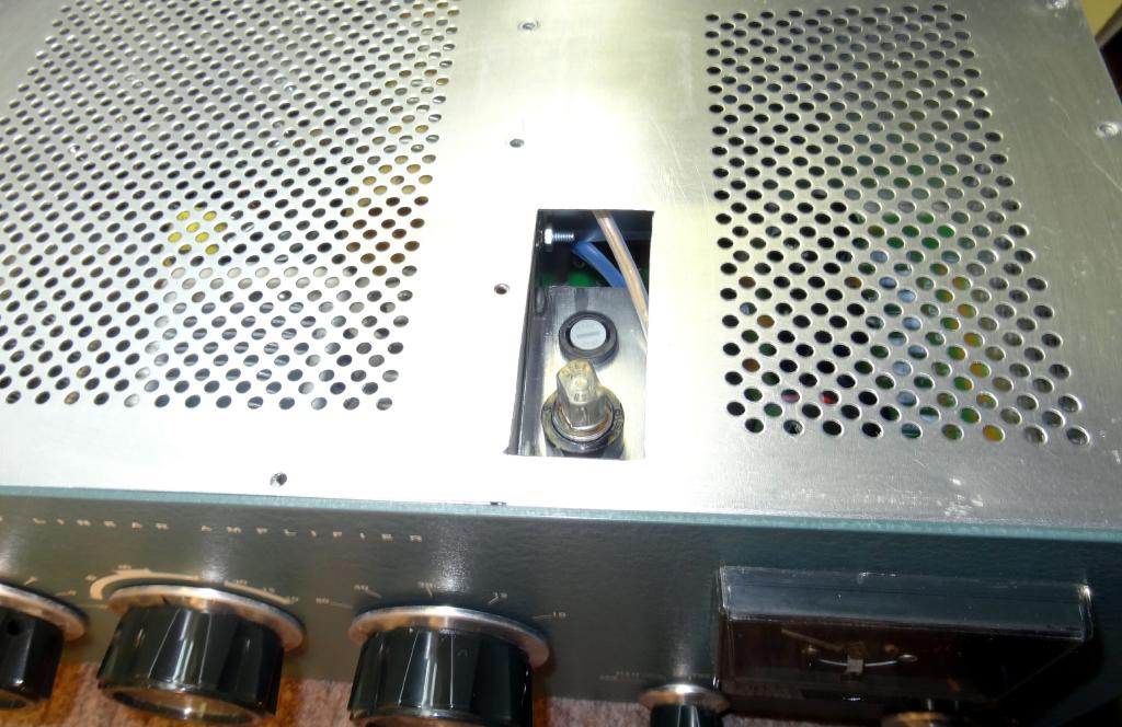 Rectangular hole cut in top cover for fuse access.
Room to install additional items in the SB-200 is limited. One area that is difficult for mounting is the underside of the power transformer. Holes cannot be drilled or screws installed because the transformer takes up a large part of the right rear of the chassis. I got around this by mounting an aluminum plate using the transformer mounting screws spaced off of the chassis to allow further mounting of components on the plate. The power relay and SoftStart board were mounted on this plate. This keeps almost all of the SB-200 primary circuits in this one area. The power relay is mounted using optional plastic mount purchased with the relay. This is screwed to a vertical plate fashioned out of aluminum and bolted to the base plate. The SoftStart board supplied instructions show mounting upside down with the relays silicone glued to the chassis. I drilled holes in the board and offset the large resistors to accommodate the screws. Nylon spacers were used to mount it to the base plate. Note that the 10W resistors on the SoftStart board need to be changed when using 120VAC vs. 240VAC. For 240VAC they are 20 ohms each and for 120VAC they are 10 ohms each. Resistors are available from Harbach.
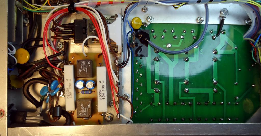 View showing the primary wiring and high voltage board.
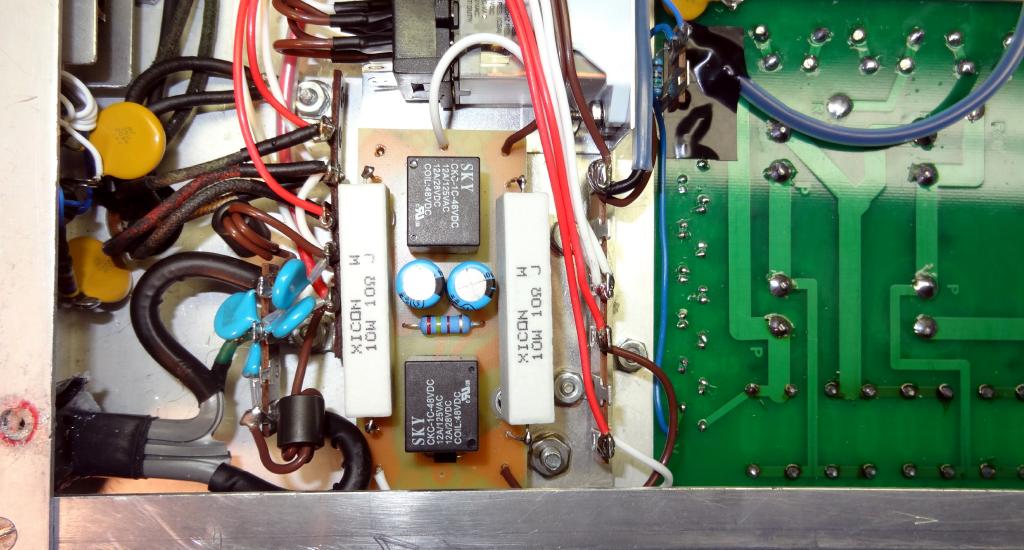 To the left is the RFI filter, the SoftStart board is in the middle, and the power relay is at the top middle.
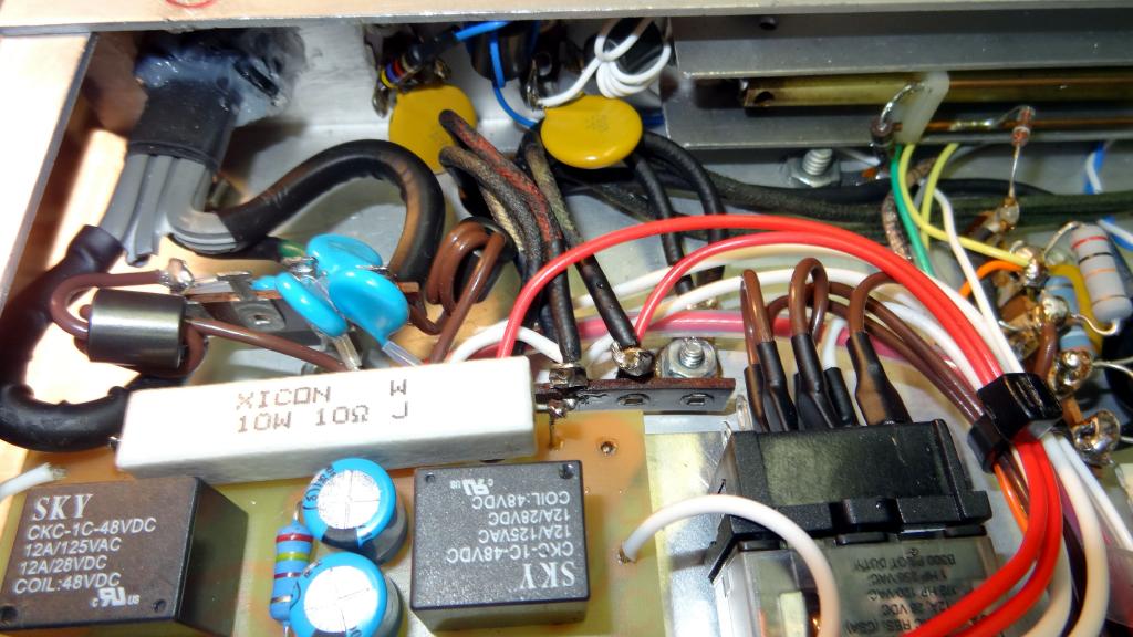 Another view of the RFI filter, SoftStart board, and power relay.
The original “record player motor” fan was removed to make way for a new 12VDC muffin fan. This required cutting a round hole in the chassis below the final tubes. The easiest way I found to do this was to use a rotozip tool with a cutting blade. It makes a great deal of metal particles and dust so I used painters tape to mask off the area and contain the particles. The tool running at high speed cuts the aluminum like a knife cutting butter. You basically freehand cut the circle and if you are careful it comes out very nice and takes about 5 minutes.
The 12V fan gets its power from the control board. There are two resistors you can select for fan speed. One selects the standby speed and the other the maximum speed during transmit. The values I selected are shown in the schematic but these could be changed to suit your needs. They would probably have to be changed if you used a fan that had different current requirements. There is a tradeoff between fan noise and cooling capability but this fan is definitely more efficient than the original. It blows more air over a larger area.
The control board rectifies and filters the 12V and negative supply which is further regulated to an adjustable -.2 to -5 volts for working bias. This board also supplies the meter LED voltage, two levels of fan voltage, and bias voltage for the ALC. A MOSFET is used to key the control and antenna relays. The maximum voltage on the rear panel key jack is about 15V and the keying current is less than one milliamp., so this is usable with any transceiver.
The antenna relay is mounted in the vicinity of the original relay but is mounted using an aluminum bracket that wraps around the relay. This has the added effect of shielding the relay. The coax lines are all Teflon, RG316 and RG400. Teflon is so nice to work with and as you can see very easy to solder and make a good ground on the shield. The shielded leads for the forward and reverse indication to the front panel meter were also replaced with RG316.
The original Heath PA bias circuitry was routed through the antenna relay and the key line would ground this line with a small value resistor. This applied a high negative voltage to the tubes in standby and hopefully gave about 90ma of operating current in transmit. It was not variable. It also applied a high negative voltage to the key jack which is not compatible with the solid-state keying in modern rigs. I used the original bias winding rectified and filtered with a resistive voltage dropping network to give about -58 volts of standby bias. In transmit the relay on the control board switches the negative regulator in parallel with the standby bias with a 47 ohm resistor to ground. This shunts the -58 supply and the operating bias becomes just the adjusted output of the negative regulator. The regulator circuit has a pair of diodes in series in the output. This raises the minimum adjustable level getting it down close to zero volts. It also limits any backward current flow from the standby bias supply into the regulator.
 Preparing to cut the new fan opening. Some rewiring already started. Good view of the aluminum plate offset mounted on power transformer mounting screws at lower right.
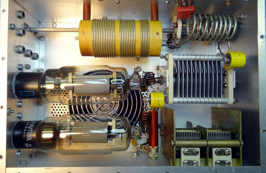 Top view showing the fan installed with grill on the top side of the chassis.
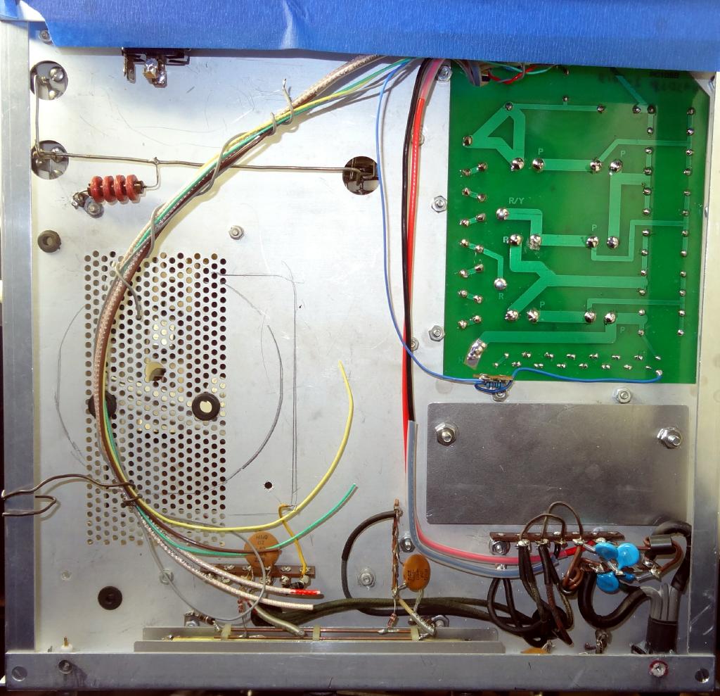
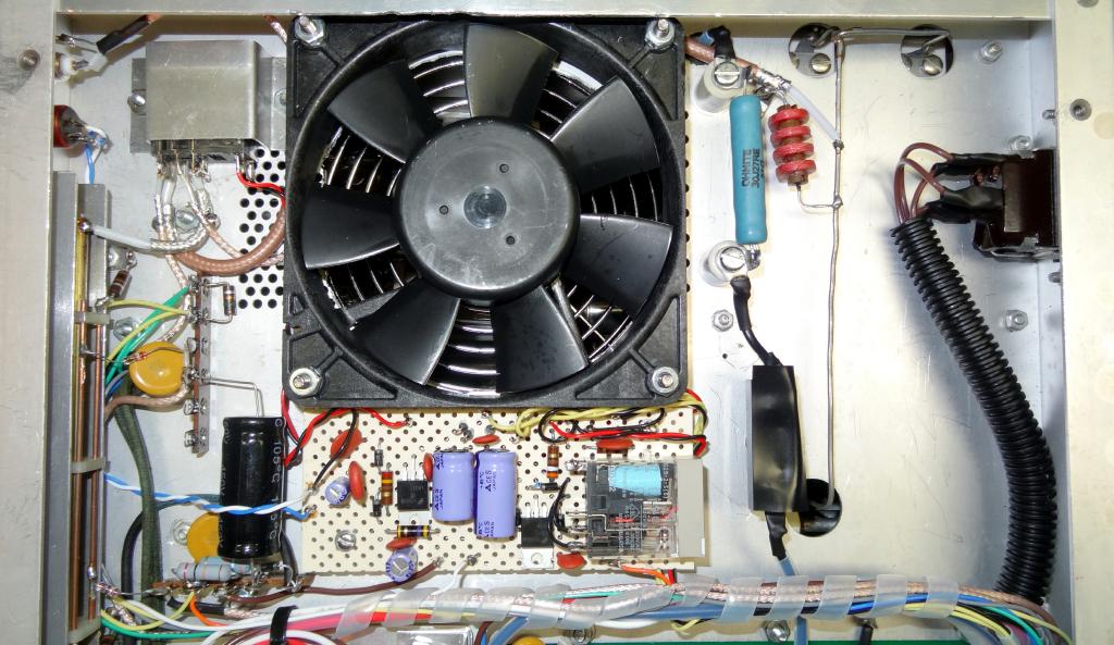 Underside of chassis showing the fan installation. The control board is mounted on nylon standoffs just below the fan. Antenna relay at upper left. BNC input connector and bias adjust pot on rear panel far upper left. On the right is the high voltage fuse mounted on an insulated standoff and the series resistor on ceramic standoffs. The high voltage wire is rated at 18kV installed in teflon tubing. Yes a great deal of overkill but it looks nice! In this photo the fuse has a piece of electrical tape over it.
The original plastic tube sockets were worn and loose I happened to have a couple of nice ceramic sockets in my junk box. The plastic sockets were held in by a piece of round spring metal and the sockets had a key to keep them oriented properly. The ceramic sockets required a much larger hole and I happened to have the right size. After mounting the tube sockets the grid bias and ALC circuitry were reinstalled along with a new terminal strip and adjustment pot. ALC bias voltage is taken from the +12V supply and a zener is used to regulate it to +10V. The Heath circuit took this voltage from a divider resistor at the bottom of the filter bleeder. Since I had this low voltage available it made more sense to not use the Heath approach which could allow the ALC bias potential to soar quite high if a resistor opened on the HV board. The new filament choke is installed along the bottom after relocating the terminal strip to accommodate the longer choke. It was supported against the outside chassis with hot glue.
 One ceramic tube socket installed.
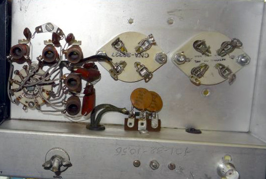 Both ceramic tube sockets installed.
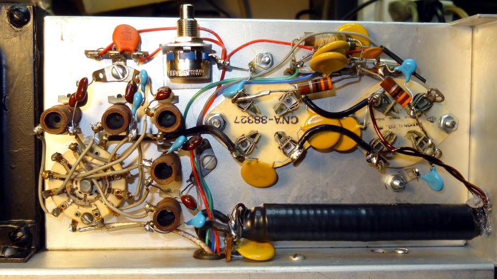 Completed rear panel area. ALC level pot and bias circuitry at upper left, new filament choke at bottom right.
A note about tubes
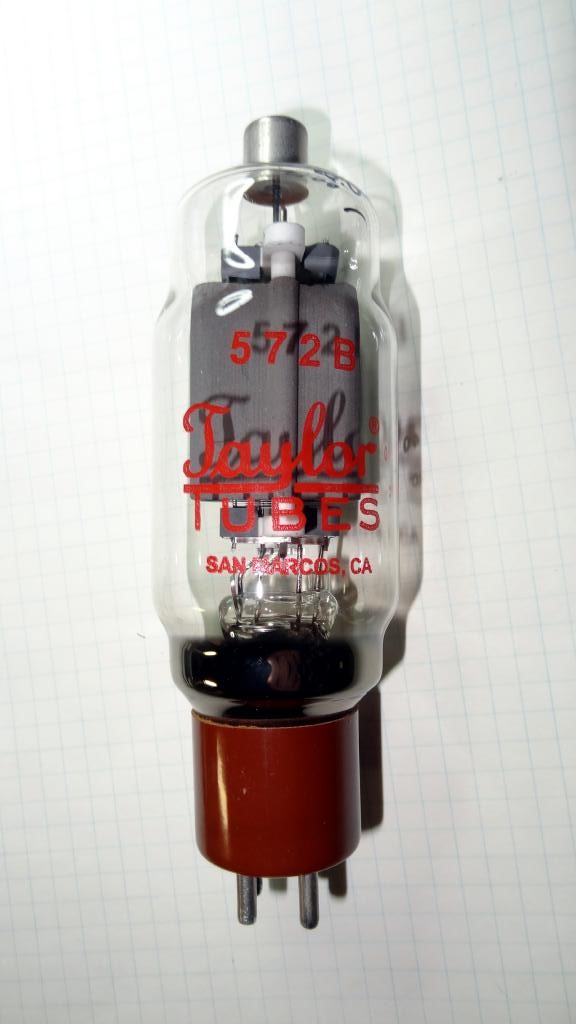
It has become increasingly hard to find good 572B tubes. As of 3/2013 they are only manufactured in China and most likely only at the Shuguang plant. Some NOS and used tubes still circulate around but like the Chinese tubes you take a chance on the condition and quality. If you are buying new tubes you can buy tubes directly from China on Ebay or through RF Parts Company in San Marcos, CA. They claim to do 100% testing of the Chinese tubes which are stamped with the Taylor name. RF Parts bought the Taylor name and uses it on tubes they sell. It has no actual connection to the original Taylor tube company which made quality tubes in the US.
My limited experience with RF Parts is that not all tubes they send out are good. I have seen reports in the forums about this. I bought a matched pair of 572B's and one was bad out of the box. RF parts blames it is shipping but lets face it what else could they say. If they do 100% testing it has to be good when they put it in the box to ship. The tube I received that was bad had low emission in a DC test that I perform on the tubes. Further inspection visually showed that the filament was not equally brilliant along its length. Some areas were quite bright and others rather dim. While anything is possible it would appear to me that this was a manufacturing problem rather than shipping. Fortunately RF Parts stands behind their warranty and they sent me a new matched pair of tubes. It is just very aggravating to pay a great deal of money and get something that is far below the US quality of the past.
The circuit I used to test the tubes was copied from PA0FRI's website on the SB-200. See the references below for additional SB-200 information. I have copied that portion of his site here. You never know when a site is going to go dark for one reason or another so it is good to have things in multiple places.
From PA0FRI's site -
To avoid flashover in a new or a long time unused tube, it is prudent to prepare ("reactivate") it for this task. There are various opinions and solutions how to do it, but with a 572B it can be relatively simple. A DC of 40 to 50 V is sufficient for the tube to draw 250 mA as the grid is connected to the anode. Heat the tube 30 minutes with a filament voltage of 6.3 V. Then supply a "high voltage" of about 45 V and set the voltage to a current of 250 mA. With a new or good 572B a current of 250 mA should occur at 44 - 45 V. If possible use a current limiter, because during reactivate the current can increase suddenly so that continue monitoring could be necessary to maintain 250 mA. Usually I will not reactivate longer than an hour. Soon you will find out at which voltage a good tube drawn 250 mA, so you have an indication if another tube is better or not. All good used or new TAYLOR, WATERS and CETRON tubes that I could test were remarkably similar, as they were 250 mA at 44 Volts.
Note the schematic above taken from PA0FRI's site should read +45 volts not +/- 45 volts.
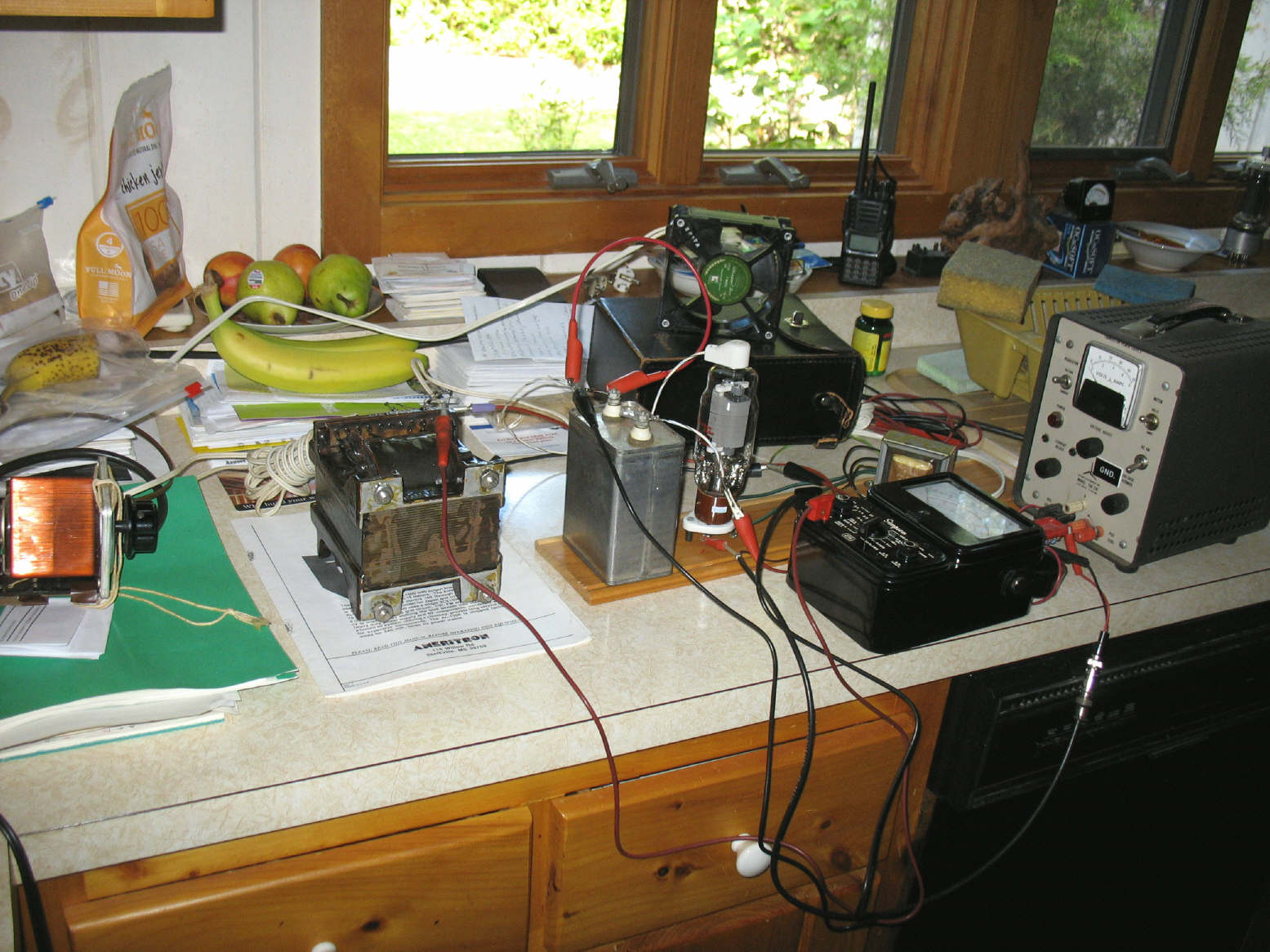
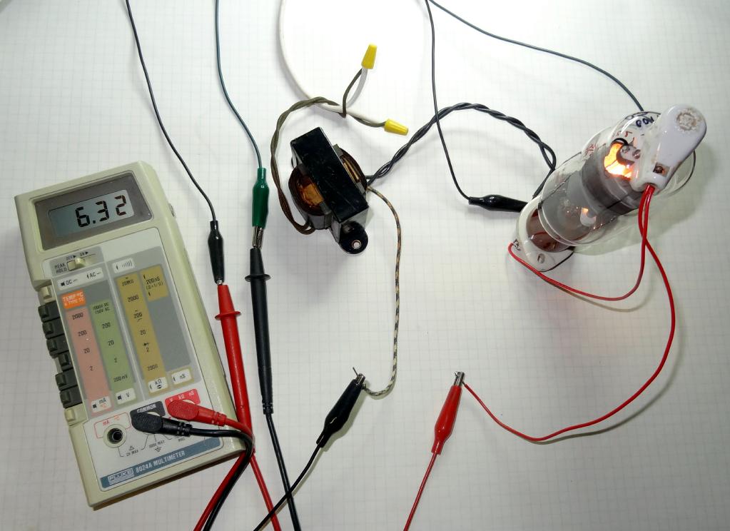 This is my haywire test jig with a 572B under test. As you can see from PA0FRI's schematic the plate and grid are tied together and positive voltage is applied between the plate and the filament center tap.
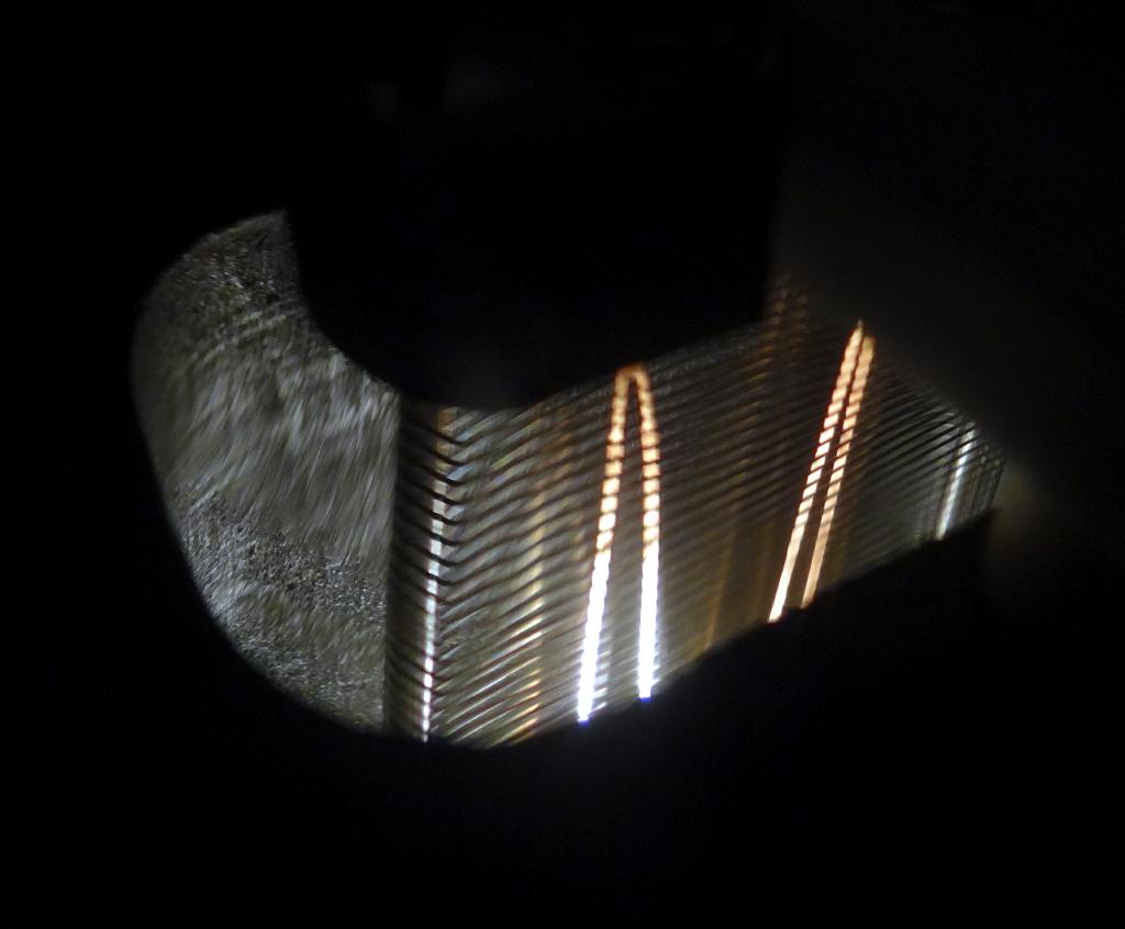 Closeup of the defective 572B with unevenly lit filament.
My SB-200 came with two worn looking Cetron 572B's. One of the plate caps had fallen off which I repaired with some high temperature silicone and solder. I tested these tubes in the test jig after burning them in for at least 30 minutes with just filament voltage. One tested at about 48 volts for 250ma and the other was about 51 volts. The good RF parts Taylor Chinese tube I received tested at about 45 volts for 250ma which is considered a good tube. I was able to achieve about 500 watts output with the worn Cetron tubes but since they are far from balanced I only intend to use them for test purposes.
My test setup consisted of a 6.3VCT filament transformer run from a variac. I set the filament voltage at 6.3V using a digital meter and monitor it during the test. The DC comes from a 0-60 VDC regulated supply that also has current limit. I set the current limit to about 260ma and raise the voltage until the tube is drawing 250ma. I then check the voltage from plate to filament. Higher values of voltage above the 44-45 volt norm indicate lower emission. As a point of reference I tested an old 811 that I had sitting around. It measured 42 volts at 250ma.
The original 572 had a maximum plate voltage of 2500V. Since the clone Chinese tubes are at least thought to be not as good as their American predecessors it would be unwise to try and push them or “hotrod” the amplifier. My SB-200 runs at about 2200-2300V unloaded and drops to somewhere around 2100V loaded. I am quite happy with this. The difference between 600 and 700 watts or 700 and 800 watts output is in the noise at the receive end but uses a lot more energy and decreases the longevity of these clone tubes. Many amplifiers run the 572's at 2700v or more. There is little margin for error at that voltage and flash overs and resulting damage often occurs. If your power transformer serves both the high voltage and the filament voltage as it does in the SB-200 you need to monitor the filament voltage. Most AC line voltages are higher today than when this rig was first designed. Checking the filament voltage with a good digital meter and keeping it close to 6.3VAC will also keep the high voltage within range.
Tube Epilogue
Hopefully this will be the last word on the tubes. The first Taylor “matched pair” from RF Parts yielded one bad and one good tube. The bad tube having a visibly defective filament and low emission. The second replacement “matched pair” was from a completely different lot. RF Parts marks the tubes with a lot number and their emission check numbers. The filaments of both tubes looked good but the emission numbers I measured were a bit different. One measured 46 volts at 250ma and the other 49.5 volts at 250ma. Not very matched in my book but then my tests are different than RF Parts. I wish they would publish how they do their tests so some comparisons could be made.
The lucky thing is that the one good tube in the first shipment had the same emission readings as the better one in the second shipment, 46 volts at 250ma. So I decided to use those two tubes and send the other two back. RF tests yielded over 600 watts output at 60 watts drive. Now the big test, some extended operation in real QSO's. One other note, the plate cap on the RF Parts Taylor 572B tube is smaller in diameter than the old Cetron tubes I have. The Cetrons measured in at 14.5mm diameter and the Chinese Taylor's at 13.9mm. That does not sound like much but if you use a ceramic push on cap it is very loose on the Taylor tubes. In my SB-200 I use a compression clip so it can be bent to make it tighter.
More late tube info -
As of September 2013 it looks like RF parts no longer carries the 572B. It is no longer listed on their website. They do list 3-500Z's and 811A's. Recently there has been talk about the Golden Dragon brand of tubes from the UK. PM Components is the distributor there. They list a matched pair of 572B's for $149.99 plus $8 shipping. The claim is that although these tubes are still manufactured in China they are spec'ed to strict PM components specifications. Others have bought them directly from China with success. If anyone has further information on this please email me at my QRZ address so I can update this page. I am particularly interested in availability and of course quality.
- PM components website - distributor
- tube-shop.com website - you can buy here
 W3JW's 572B Burn-in Jig. See his comments below. It goes without saying that when testing like this you need to exercise extreme caution around the high voltage.
Jeff, W3JW shares his 572B re-gettering approach:
"This is the quick setup I used to check out the Shugang 572B's. Not very
elegant, but got the job done. On the left you see the small variac I used
to adjust the plate voltage. Then the plate transformer and rectifier, the
filter capacitor the tube under test and it's filament transformer. The
bench PS to the right was used to provide positive grid voltage to cause
150 MA plate current to flow in the tube (at just over 1000 V DC). This
amount of plate dissipation caused the plate to glow a very dull red (takes
30-45 seconds for color to start to show).
When I did the 3-500Z's it took 250 ma at 1000 V. I did 10 cycles of 2 to 3 minutes with plate voltage on
and 5 to 6 minutes plate voltage off (to keep the glass seals within spec. I did the 3-500 Z's right in the
AL-80 B as it has the necessary HV transformer taps to implement 1/3 and 2/3 of full 3KV voltage.
It also has a fan to keep the tube cooled. For my 572B test I will place a muffin fan (directed towards the tube) a few inches away.
I have completed one of the tubes and will do the other one this afternoon;
it takes about an hour to complete."
I used a similar approach only I use a dummy load and RF to condition my tubes. I used a Kenwood TS-430 and set the carrier control to give about 200 watts carrier output on 75 meters. This resulted in a dull red tube glow. I then followed the cycling procedure as W3JW did. If you do it this way be careful that you do not exceed the temperature limit of your dummy load. I have a massive Bird unit that takes a long time to heat up.
W8JI has some good info on this procedure HERE. Be sure to check it out before performing a burn-in of your tubes.
Hopefully the final word on the 572 tubes
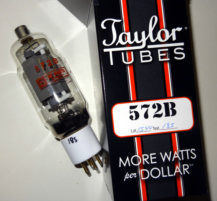
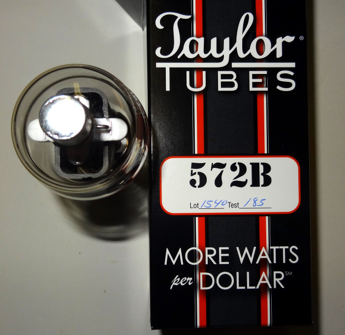
In 2015 RF parts found another Chinese company to make the 572B tubes. Under their strict requirements a tube was made that according to them was at least as good as the former Cetron tubes made before 1990. After my set of Shuguang tubes that I purchased for this project failed in early 2016 I bought a matched pair of the new tubes from RF Parts. They look good with ceramic bases and RF parts guarantees them for one year. So far no problems. I get a full 600 watts output on 75 meters with 60 watts of drive. Here are some photos of the new tubes as they arrived.
 And finally as I do with all my restorations here is the photo of all of the leftover (replaced) parts.
All were stock parts except for the relay, electrolytics, and toroid line choke at the lower right.
Schematics and Reviews
- Heath SB200 schematic
- Heath SB-200 manual
- eHam SB-200 review
- AF6C Heath Review
- Index of articles appearing in QST for Heath linear amplifiers 1965-1995
- Complete WA3DSP modification Schematic
Schematic Notes
My original modification schematic had a couple of errors that have now been corrected. In addition I had a problem with HV fuses blowing. I started out with a ˝ amp which lasted for many months. I then tried a 1A and it blew almost immediately. I suspected a possible flash over so I conditioned the tubes as described above which seemed to solve that problem but the flash over may have damaged the bias regulator. I added some protective diodes in three areas as shown on the updated schematic. I am currently using a 2A HV fuse which might be too large but the original SB200 circuit used no fuse or series resistor so this is certainly a step in the right direction. The HV filter capacitor could develop very high current spikes in the event of a short and both the resistor and the fuse would go a long way in helping to preventing circuit destruction.
Some resources that I used during this restoration -
Parts used
Besides the normal resistors, capacitors, diodes, etc.
- Power Control Relay - 782XBXC-120A Magnecraft - Mouser
- Control and Antenna Relays - G2R-2-S-DC12(S) Omron - Mouser
- MOSFET PTT - 512-FQP8P10 - Fairchild - P channel 100V - Mouser
- Regulator LM337 - Mouser
- Ferrites - FB63-77 Amidon
- Transformer - 25.2VCT @ 450ma. - Radio Shack 273-1366
- Cooling Fan - Comair-Rotron Flight II FT12B3 - 4.75" square, .85" 25mm thick. Available here
Many newer fans avaialable with these dimensions at Newark, Mouser, etc.
Parts Reference
- Mouser - relays, resistors, capacitors, MOSFET's, zeners
- Radio Shack - 273-1366 transformer
- Apex – Teflon wire and tubing, coax, surplus electronics
- Harbach Electronics - Power Supply and SoftStart boards
Circuit and Design References
- PA0FRI SB-200 Modification page
- KL7FM - SB-200 notes
- W0ANM SB-200 blog
- K0GKD SB-200 review and notes
- AE1S SB-200 Restoration
- N4NAB Restoration Notes
- N7IPY SB-200 Rebuild
- M0UNI - SB-200 Restoration
- NT1K SB-200 Project
- Various Heathkit Links
- SB-200 Sleeper - pressing the limit
- Amidon - Ferrite cores for RFI suppression
- Electric Radio Magazine - February 2013 - Page 34 - The HB600 Linear Amplifier - Mike Bohn, KG7TR
- The Amateur Radio Handbook - multiple years
- Original Cetron 572B Data
- O'Malley 572B Data
- Svetlana 572B Data
- RCA Transmitting and RCA receiving tube Reference
- Shuguang Factory Tour - Where the 572B's are made now.
- Another look at the Shuguang Factory
Chemicals Used
- Krud Kutter
- Deoxit D5
- Deoxit gold
- WD40
- Windex (The Greek wedding micracle fluid!)
I give full credit to those whose modification ideas preceeded mine and that I have used in this restoration. Special thanks to Mike Bohn, KG7TR. His timely Linear Amplifier article in ER and our email correspodence helped immensely.
73, Doug
I have made an attempt to present my work here so that others could benefit. Hopefully I have written an understandable document. I welcome constructive criticism. If you don't understand something I would be more than willing to answer any questions you may have. Just email me at my QRZ email address.
This page last updated 10/24/2016
© 2013-2016 - WA3DSP