RME-6900 Restoration
RME History
In 1931/32 Radio Manufacturing Engineers was founded by E.G. Shalkhauser (W9CI) and Russ M. Planck (W9RGH), they started producing their first receiver RME-9 in 1932. In 1943 the company moved to 313-315 Bradley Ave and in 1935 to 306 First Ave., Peoria, Ill.,where the company's most famous set, the RME-69 has been produced.
After the War, RME merged with Electro-Voice, Buchanan, Michigan; Planck stayed with the company and supervised the design of a new series of shortwave receivers under the name of Radio Mfg. Engineers, Div. of Electro-Voice Inc. In 1962 RME Division has been taken over by G.C. Electronics of Rockford, Ill., the name of RME disappeared within a year.
Electrovoice's founder, Albert R. Kahn (K4FW SK) along with Jack Burchfield, (K4JU) later went on to form communications company Ten-Tec in 1968. Mr. Kahn became a Silent Key in 2005. I found no history telling of possible influence that Kahn or Electro-voice would have had on the RME-6900's design but I am sure there was some connection.
RME-6900 Restoration Project
(Click any photo to see a larger view)
This was a quick restoration as this receiver was basically in very good condition. The chassis top was dirty and I used the simplegreen aircraft cleaner to restore its luster. After carefully drying things out over several days in a low humidity environment I then went on to complete the restoration.
I discovered that the calibrate knob was frozen and would not move. It is a three position switch that selects 100Khz calibrate with or without the antenna connected or a center position that is normal receive operation.
 The switch was really frozen tight. Spraying and using a wrench would not budge it. The shaft was disengaged and the front section of the switch was removed.
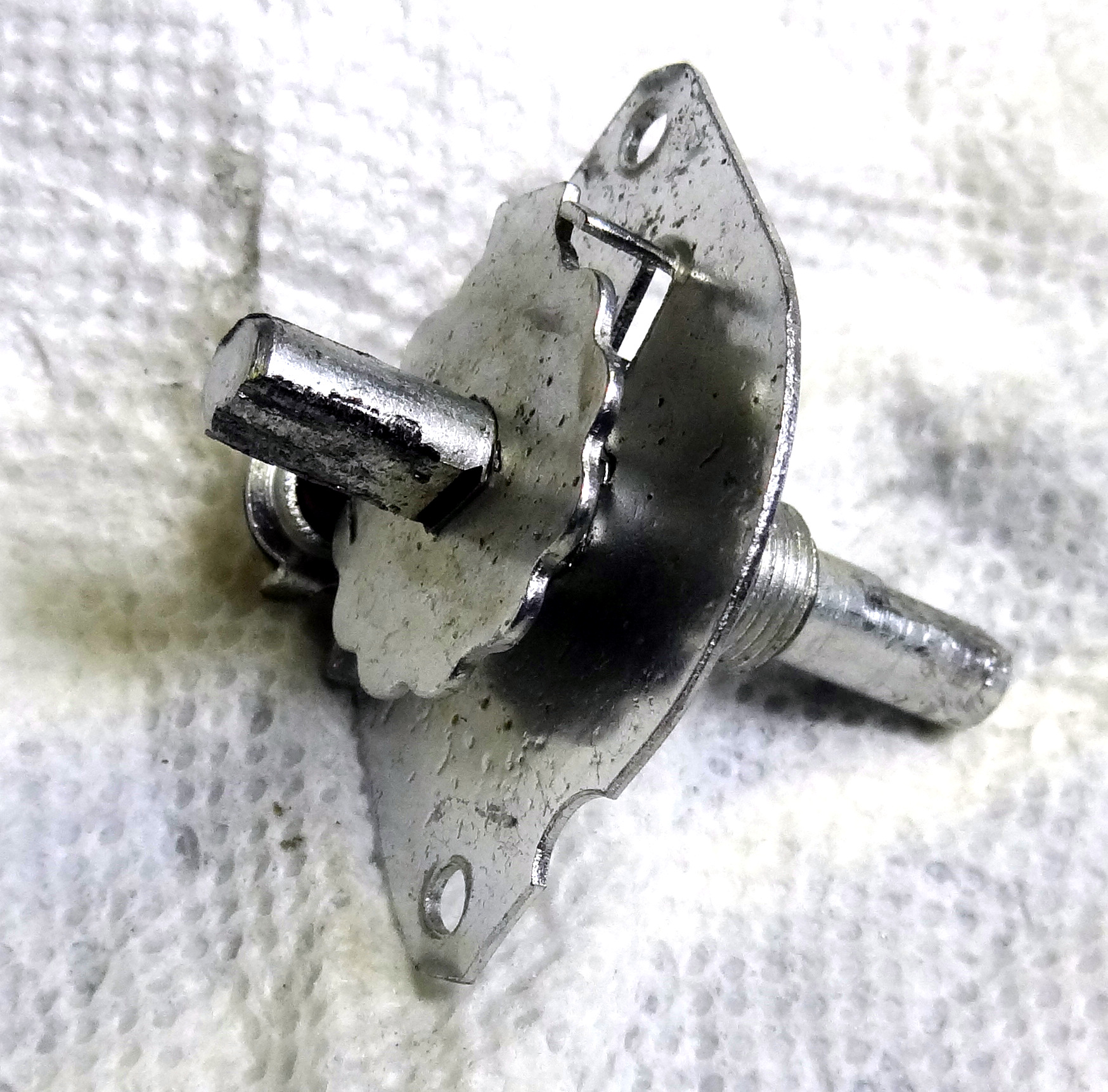 After removal I dried various sprays but it was really locked. I finally used heat from a heat gun in combination with WD-40 and broke it loose. It was then reinstalled and it worked perfectly.
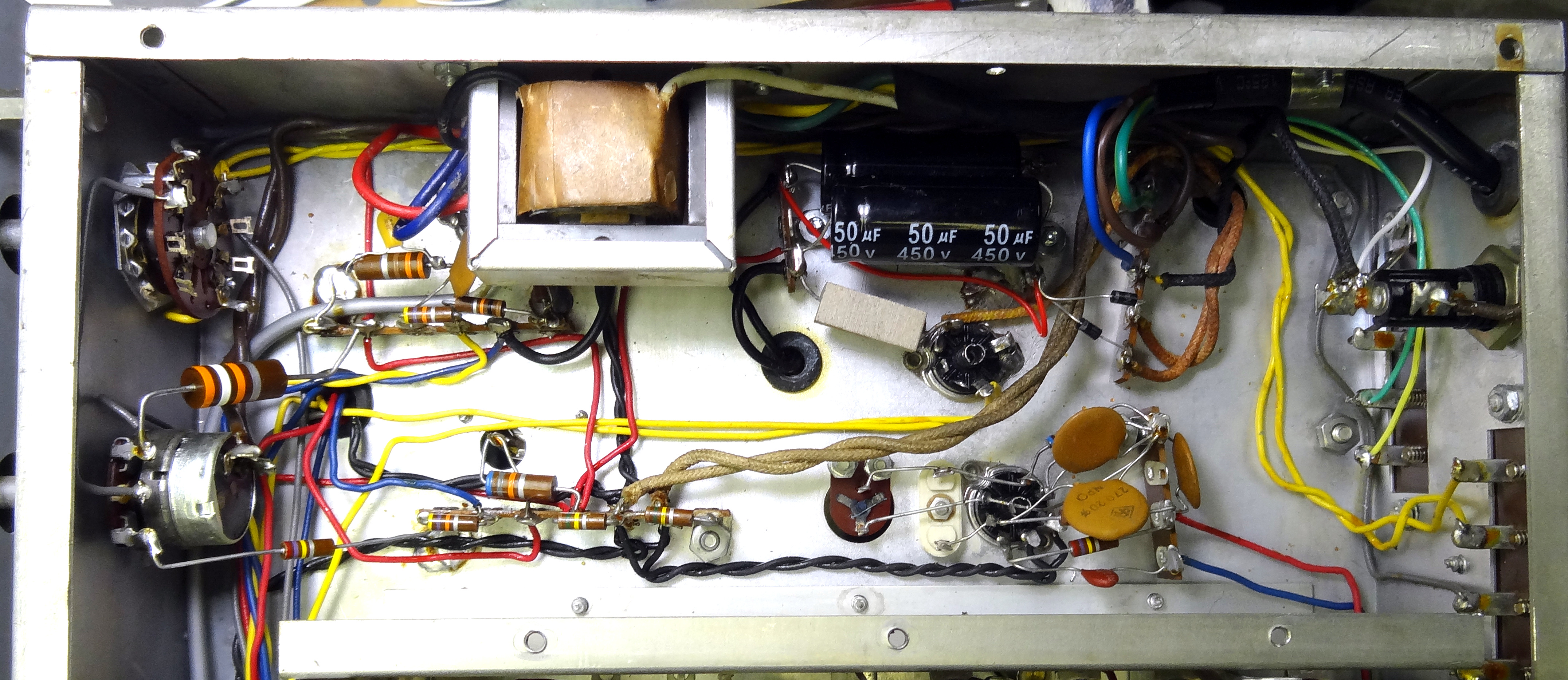
I decided to replace the can electrolytic. It is shown in the following photo with its three case tabs soldered to the chassis. I used a large solder gun to heat and remove. Also you can observe that the audio output transformer has been removed from the side of the chassis for better access. There is also no line cord at this point as the old two wire plug and cord have been removed.
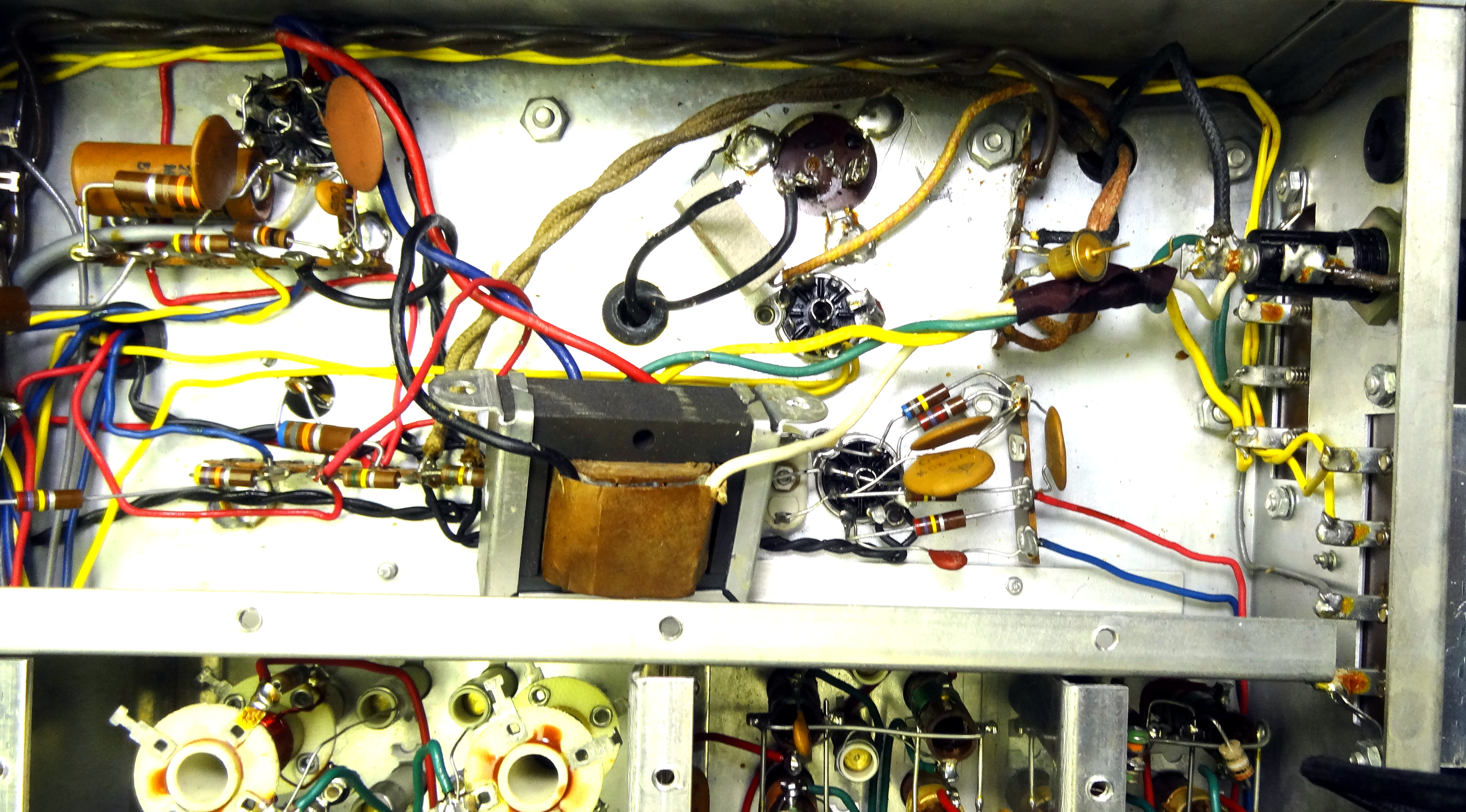 View showing Can electrolytic from the bottom before removal. The old "top hat" rectifier diodes were also replaced.
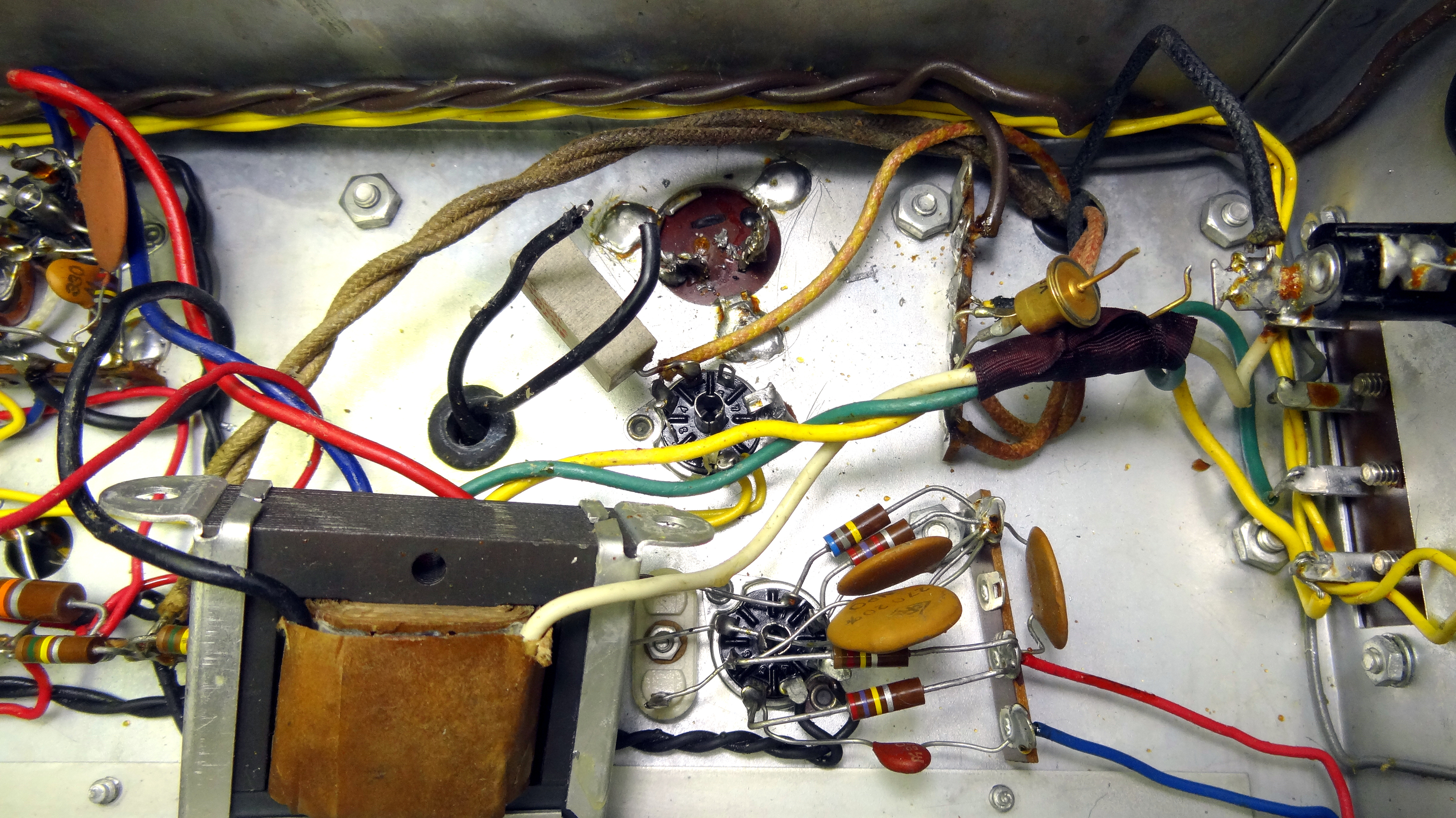 Closer view of power supply area.
Following photos show the power supply section after modification. The can electrolytic was removed and an aluminum plate installed to cover the hole. Two three terminal strips were installed below the chassis using the same screws that holds the plate. The power supply was rewired using two 50uf 450V electrolytics and new 1A 1000V diodes.
 View of the completed power supply update. Also note the small replacement electrolytic across the audio output cathode at the left.
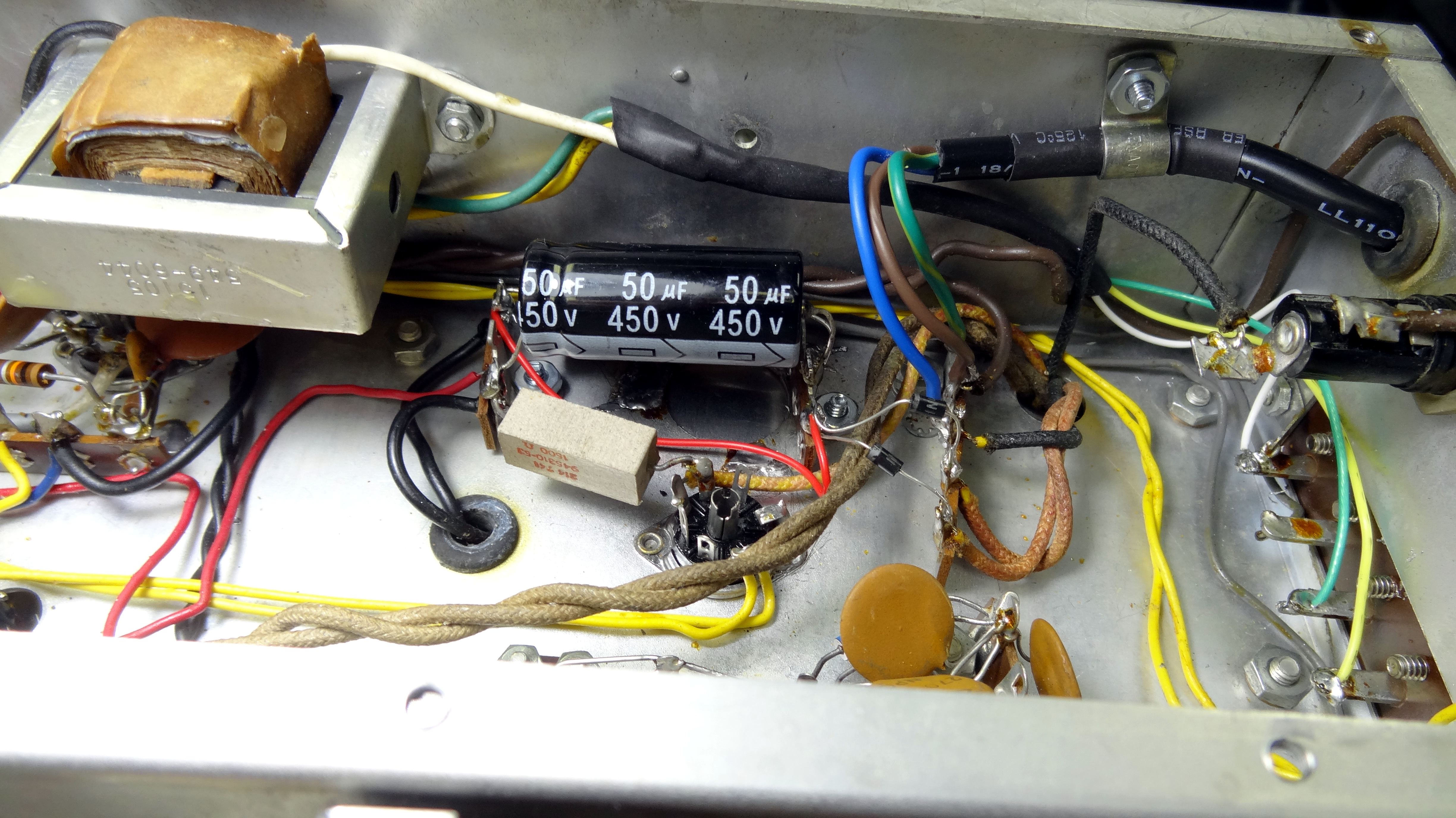 Closer view of the finished power supply area. The audio output transformer has been moved forward on the side chassis and its wiring to the back panel extended. The second electrolytic is hidden behind the one you can see. A new grounded line cord in place with clamp on the side chassis.
Along with the filter electrolytic several other electrolytics were replaced as well as a couple of tubular capacitors. This was just a preventative measure. All of these capacitors tested good unpon removal but were replaced with newer, smaller, and higher quality capacitors. The line cord and power supply diodes were replaced. In general everything else was in very good shape. This is typical of radios of this era (1960+) as available components had become much more reliable.
Final Checkout
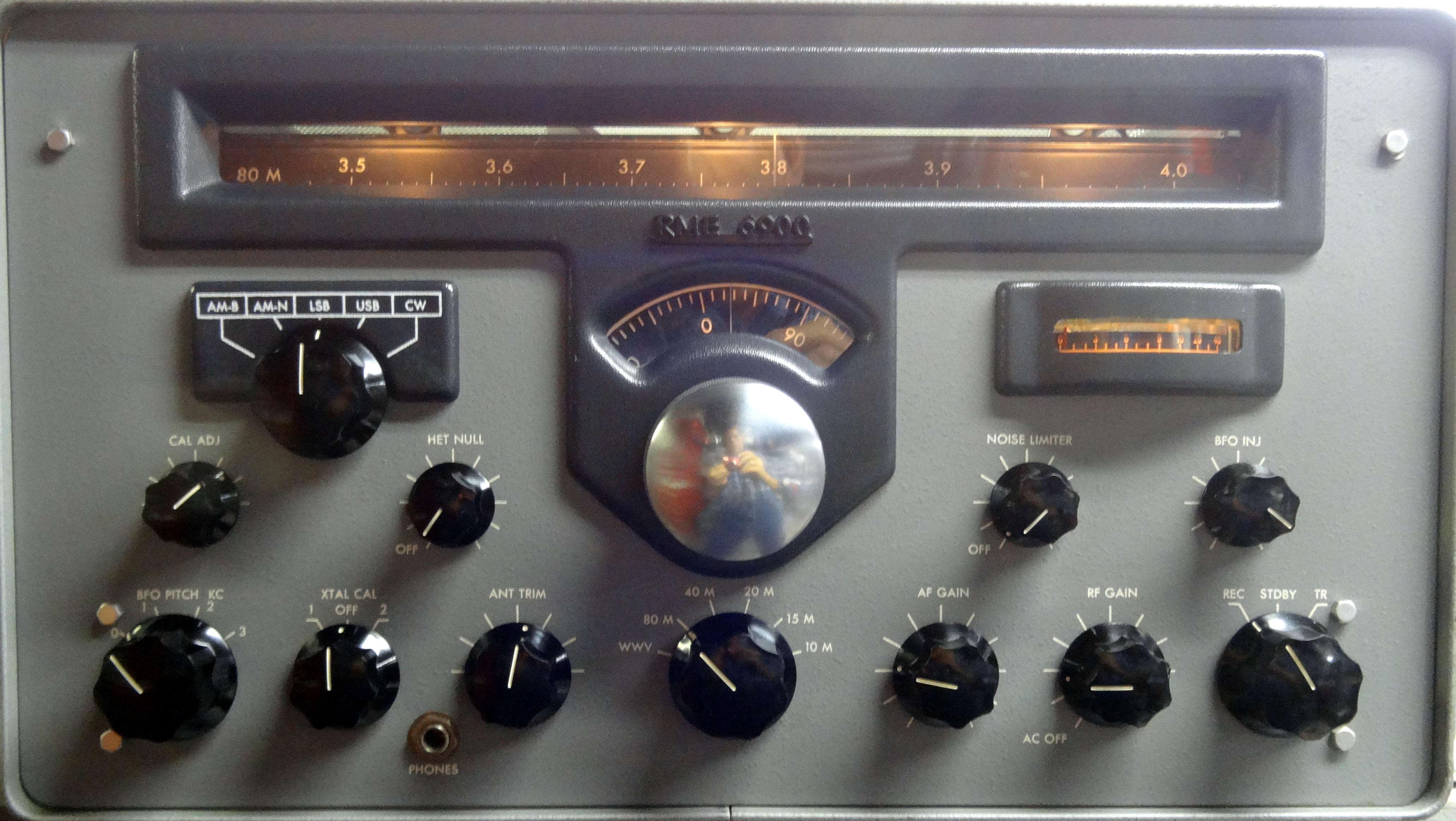
I was actually quite impressed with this receivers performance. It is quite stable and receives SSB quite well. It has a product detector and upper/lower SSB selection. I quess I would put it somewhere in the class of a Hammarlund HQ-170 in that respect. It is physically smaller than an HQ-170. I was not enamored with the tuning calibration though. It has a drum like megahertz dial like the Heath Mohawk or Collins 51J. This dial can be calibrated to the nearest 100khz with the calibrator but there is no such calibration for the band-spread dial. You can align the receiver at the band edges for 0 on the band-spread dial but the intermediate settings are wrong. Since the megahertz and band-spread dials are mechanically connected it seems the ratio between them is off. So one really has to guess exactly what frequency you are on using the closely calibrated megahertz dial as a guide. It has good and plentiful audio and I was happy that they don't run the B+ up to ridiculous levels like some older radios do. The highest B+ is about 170 volts.
RME Radio Links
- RME-6900 Manual and Schematic
- Wikipedia Electrovoice
- A brief history and products of RME
- Radio Museum RME History
- Radio Works RME-6900 critique
- Youtube Demo of the RME-6900
This page last updated 1/10/2022
© 2022 - WA3DSP